
Door access control system wiring diagrams provide a visual representation of how components connect, ensuring secure and efficient installation. They guide installers through power supply, lock, and sensor connections, promoting safety and compliance with regulations. These diagrams are essential for understanding system architecture and troubleshooting issues effectively.
What is a Door Access Control System?
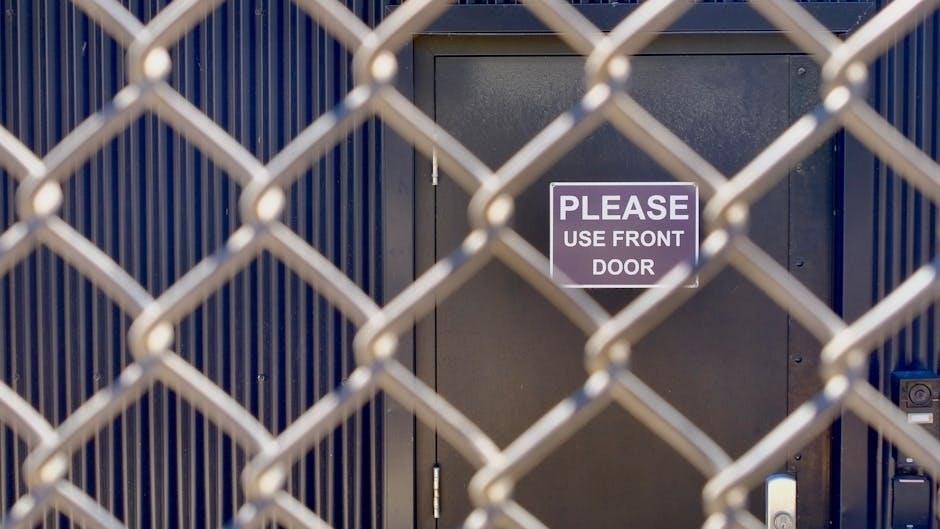
A door access control system is an electronic solution designed to manage and regulate entry into secure areas. It integrates components like locks, sensors, and readers to ensure only authorized individuals gain access. These systems enhance security, convenience, and efficiency by replacing traditional keys with advanced authentication methods such as keycards, biometrics, or PINs. They are widely used in residential, commercial, and industrial settings to monitor access, prevent unauthorized entry, and maintain operational continuity. The system’s functionality is tailored to specific security needs, ensuring reliability and scalability for various applications.
Why Wiring Diagrams are Essential for Installation
Wiring diagrams are crucial for installing door access control systems, as they provide a clear visual guide for connecting components. These diagrams outline the relationships between power supplies, locks, sensors, and readers, ensuring proper installation. They help installers avoid errors, which is critical for system functionality and safety. By following the diagram, technicians can efficiently connect devices, reducing the risk of miswiring. This resource also aids in troubleshooting and ensures compliance with electrical standards, making the installation process safer and more efficient. A well-detailed wiring diagram is indispensable for a successful setup.
Key Components of a Door Access Control System
Power supply units provide the necessary voltage for system operation. Door locks ensure secure access control. Readers and sensors manage authentication and monitoring. Wiring and hardware connect all components seamlessly.
Power Supply and Voltage Requirements
A stable power supply is crucial for door access control systems, typically requiring 12/24V DC. The 12/24V 4-Door Smart Hub uses units like LifeSafety Power FPV4 to ensure reliable operation. Voltage must align with system specifications to prevent damage. DC power supplies are standard, with systems often supporting a range of 10V to 30V. Compatibility with locks, readers, and sensors is essential. Proper grounding and surge protection are recommended. Backup power sources, like batteries, are advised for uninterrupted operation during outages. Always verify voltage requirements to ensure optimal system performance and safety.
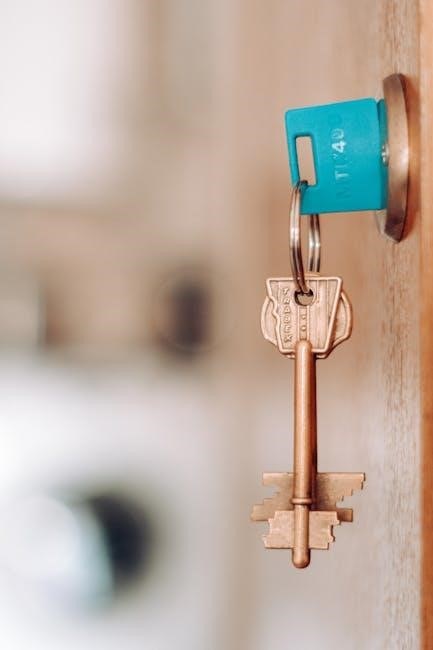
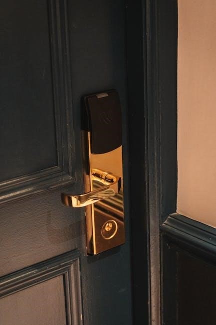
Door Locks and Their Compatibility
Door locks are a critical component of access control systems, requiring compatibility with the overall setup. Magnetic locks and electric strikes are common, operating on 12/24V DC. Compatibility ensures seamless integration with readers, sensors, and power supplies. Fail-safe locks open during power outages, while fail-secure locks remain locked. Proper lock selection aligns with security needs and system voltage requirements. Always verify lock compatibility with controllers and power supplies to ensure reliable operation and safety. This ensures smooth functionality and meets specific security demands for any access control application.
Access Control Readers and Sensors
Access control readers and sensors are essential for detecting and verifying credentials to grant entry. Readers include proximity, keypad, and biometric options, while sensors monitor door status and motion. Compatibility with locks and controllers ensures smooth operation. Proper wiring connects readers to power supplies and controllers, enabling communication. Sensors like door contacts and exit buttons provide real-time feedback, enhancing security.Correct installation and wiring ensure reliable performance, preventing unauthorized access and system malfunctions. Diagrams guide installers to connect these components accurately, ensuring seamless functionality and security. Regular testing is crucial to maintain optimal system performance and reliability. Proper setup ensures all components work in harmony.
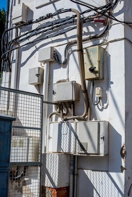
Wiring and Connectivity Hardware
Wiring and connectivity hardware are critical for ensuring reliable communication between components. Shielded cables are recommended to prevent interference. Color coding helps identify wires for power, data, and control signals. Proper connectors and terminals ensure secure connections. Avoiding splices minimizes signal loss and ensures durability. Spare conductors should be included for future expansions. Voltage drop calculations are essential for long cable runs. Proper grounding prevents electrical noise and ensures system stability. Following wiring standards guarantees compliance and performance. Secure connections prevent failures and unauthorized access. Regular inspections maintain system integrity and reliability over time. Proper wiring practices are vital for optimal functionality and safety. Always refer to diagrams for precise connections.

Safety Instructions and Precautions
Always disconnect power before starting installation. Use proper tools and follow manufacturer guidelines. Ensure all connections are secure to prevent electrical hazards. Test the system safely after completion. Follow local electrical codes and regulations. Wear protective gear when handling wiring. Avoid overloading circuits to prevent damage or fire risks. Keep the area clean and well-ventilated during installation. Ensure proper grounding to avoid shock or malfunction. Regularly inspect wires for damage or wear. Never bypass safety features or disable alarms. Consult professionals if unsure about any step. Ensure compliance with all safety standards and regulations. Prioritize safety to avoid accidents or system failures.
General Safety Guidelines for Installation
Safety is critical when installing door access control systems. Always disconnect power before starting work. Use proper tools and follow manufacturer guidelines. Ensure all connections are secure to prevent electrical hazards. Test the system safely after completion. Wear protective gear, including gloves and safety glasses, when handling wiring. Avoid overloading circuits, as this can cause damage or fire risks. Keep the work area clean and well-ventilated. Regularly inspect wires for damage or wear. Never bypass safety features or disable alarms. Consult professionals if unsure about any step. Adhere to these practices to prevent accidents and ensure system reliability.
Electrical Safety Measures to Avoid Hazards
To prevent electrical hazards, always switch off the power supply before handling wires. Use a multimeter to confirm zero voltage. Install surge protectors to shield against power spikes. Ground all components properly to avoid shocks. Keep wires away from high-temperature sources and flammable materials. Ensure all connections are tight and insulated. Regularly inspect for worn insulation or frayed wires. Never overload circuits, as this can cause overheating or fires. Use appropriate circuit breakers and fuses. Ensure compliance with local electrical codes. Follow these measures to safeguard personnel and equipment from electrical risks during installation and operation.
Understanding the Wiring Diagram
A wiring diagram is a visual guide illustrating connections between components. It helps installers understand the system’s structure, simplifying installation and troubleshooting by detailing power supply, door lock, and sensor connections.
Reading and Interpreting the Diagram
Reading and interpreting a wiring diagram requires understanding its symbols and connections. Start by identifying the power supply, door locks, and sensors. Color-coded wires simplify tracing connections. Trace each wire from the power source to components like readers and locks. Verify door lock connections, ensuring proper wiring for normal or fail-safe operations. Check sensor placements for alarm triggers. Use the diagram to confirm compatibility between devices. Follow step-by-step connections to avoid errors. If unsure, consult the manual or seek professional guidance to ensure a safe and functional installation.
Color Coding and Wire Identification
Color coding ensures quick identification of wires in an access control system. Typically, red wires carry positive voltage, while black wires are ground. White wires may signify signal outputs, and yellow often indicates alarm or sensor connections. Green wires are commonly used for door locks or relays. Refer to the wiring diagram for specific color assignments, as they may vary by manufacturer. Proper identification prevents misconnections, ensuring system reliability and safety. Always verify wire colors against the diagram to avoid installation errors and potential hazards.

Installation Steps for a Basic System
Begin by preparing the site, ensuring all tools are available. Connect the power supply to the access control hub, following the wiring diagram. Install door locks and sensors, securing them firmly. Wire the system, connecting components as per the diagram. Test each connection to ensure functionality. Finally, configure the access control settings and verify system operation to complete the installation successfully.
Preparing the Site and Tools
Before installation, ensure the site is clear of obstacles and accessible. Gather essential tools like screwdrivers, wire strippers, and a multimeter. Review the wiring diagram to plan the layout. Verify power supply availability and ensure all components are compatible. Wear safety gear, including gloves and goggles, to prevent injuries. Organize cables and wires neatly to avoid tangles. Use cable ties or management tools for a clean setup. Double-check the compatibility of all devices with the access control system. Ensure proper ventilation and a stable work surface for efficient installation.
Connecting the Power Supply
Connect the power supply unit to the access control system, ensuring the voltage matches the system’s requirements, typically 12/24V DC; Use the wiring diagram to identify positive and negative terminals. Securely attach wires to the power supply and system hub, avoiding loose connections. Install a backup battery if required for uninterrupted operation during power outages. Test the power supply with a multimeter to ensure stable voltage output. Follow safety guidelines to prevent electrical shocks and system damage. Proper connection ensures reliable system performance and longevity.
Wiring the Door Lock and Sensors
Connect the door lock to the access control system using the wiring diagram. Attach the lock’s wires to the appropriate terminals on the control panel. Install door sensors to monitor the lock’s status, ensuring they are securely wired to the system. Use color-coded wires for clarity, with positive and negative terminals clearly marked. Ensure all connections are tight to prevent signal loss. Test the system to confirm the lock and sensors function correctly. Proper wiring ensures smooth operation, security, and reliability of the access control system, minimizing potential malfunctions or unauthorized access risks. Follow safety guidelines during installation.
Advanced Configurations and Integration

Advanced configurations enable multi-door systems and integration with security features like biometrics or video surveillance. These setups often require centralized hubs or networked systems for seamless operation.
Setting Up Multi-Door Systems
Setting up multi-door systems involves configuring a central hub to manage multiple access points. The 12/24V 4-Door Smart Hub (SYS-4ENT-DVE1) is a common solution, powering multiple doors and integrating sensors. Each door requires its own lock, reader, and wiring connections, ensuring proper synchronization. The hub simplifies scalability, allowing seamless addition of doors or security features. Proper wiring and network configuration ensure reliable communication between devices. Color-coded wires and centralized control enhance system organization and maintenance, making multi-door setups efficient and secure.
Integrating with Additional Security Features
Integrating door access control with additional security features enhances overall system functionality. Solutions like exit buttons, alarm systems, and motion sensors can be seamlessly connected. Wiring diagrams detail how these components link to the central hub, ensuring proper signal flow. Advanced configurations may include video surveillance or biometric readers, offering multi-layered security. Proper shielding and grounding of wires prevent interference, ensuring reliable operation. This integration allows for a holistic security approach, addressing various threats while maintaining system efficiency and user convenience, as outlined in the provided diagrams and installation guides.

Maintenance and Troubleshooting
Regular maintenance ensures optimal performance of door access systems. Check wiring connections, clean sensors, and inspect power supplies. Address common issues like sensor malfunctions or power outages promptly using diagnostic tools and wiring diagrams to identify and resolve faults efficiently.
Regular Maintenance Tips
Regular maintenance is crucial to ensure the longevity and reliability of door access control systems. Inspect wiring and connections for wear or damage, and clean sensors to maintain accuracy. Check power supplies for stable voltage and test door locks for proper function. Schedule periodic firmware updates and database backups. Use wiring diagrams to verify connections and identify potential issues before they escalate. Replace worn-out components promptly and keep a log of maintenance activities for future reference. Regular checks prevent system failures and enhance overall security.
Common Issues and Their Solutions
Common issues with door access control systems often stem from wiring errors or component malfunctions. A faulty power supply can cause systems to malfunction; check voltage levels and ensure proper connections. If doors fail to lock or unlock, inspect door lock wiring and sensors for damage or misalignment. Refer to wiring diagrams to trace connections and identify discrepancies. Resetting controllers or updating firmware can resolve software-related glitches. Ensure all components are compatible and configured correctly to avoid operational hiccups. Regular testing helps identify and address issues before they impact security.
Best Practices for Wiring
Plan the layout to minimize wire runs and reduce interference. Use color-coded cables for easy identification and ensure secure connections to prevent signal loss or damage. Follow diagrams precisely, and test each connection before finalizing the setup. Regularly inspect wires for wear and ensure compliance with safety standards to maintain system reliability and efficiency.
Optimizing Wire Layout and Management
Efficient wire management is crucial for reliable door access control systems. Plan the layout to minimize wire runs, reducing interference and signal degradation. Use cable ties or raceways to secure wires neatly, preventing damage and tangling. Label each cable clearly for easy identification during installation and maintenance. Ensure all connections are secure and follow the wiring diagram precisely to avoid errors. Proper organization not only enhances system performance but also simplifies future upgrades and troubleshooting. Regular inspections and maintenance can further ensure long-term functionality and safety.
Ensuring Compliance with Regulations
Compliance with local and international regulations is vital for door access control systems. Adhere to safety standards like UL and EN for electrical installations. Ensure data protection laws are followed when handling personal information. Fire safety regulations must be met, particularly for emergency exits. Regular inspections and certifications may be required. Always consult local building codes and manufacturer guidelines. Proper documentation and adherence to wiring standards prevent legal issues and ensure system reliability. Compliance not only avoids penalties but also guarantees user safety and data security, making it a cornerstone of professional installations.

Future Trends in Access Control Wiring
Future trends include smart, integrated systems and wireless IoT-based solutions, enhancing security, efficiency, and scalability while reducing wiring complexity and improving system adaptability for modern applications.
Smart and Integrated Systems
Smart and integrated systems are revolutionizing access control by combining advanced technologies like biometrics, AI, and cloud connectivity. These systems enable seamless integration with existing security infrastructure, offering centralized monitoring and control. They support real-time data analysis, improving decision-making and threat response. Integration with IoT devices allows for remote management and scalability, ensuring systems can adapt to evolving security needs. Additionally, these systems reduce wiring complexity by utilizing IP-based communication, enhancing reliability and minimizing installation challenges. This approach ensures a future-proof solution for modern access control requirements, providing enhanced security and efficiency across various applications.
Wireless and IoT-Based Solutions
Wireless and IoT-based solutions are transforming door access control systems by eliminating the need for extensive wiring. These systems leverage Wi-Fi, Bluetooth, and cellular connectivity to enable real-time monitoring and remote management. IoT integration allows seamless communication between devices, enhancing security and convenience. Cloud-based platforms provide centralized control, while wireless sensors and locks reduce installation complexity. Advanced encryption ensures data security, preventing unauthorized access. These solutions also support integration with smart devices and building management systems, creating a holistic security ecosystem. By adopting wireless and IoT-based technologies, modern facilities achieve greater efficiency, scalability, and future readiness in access control systems.
This guide provides a comprehensive overview of door access control system wiring diagrams, emphasizing safety, efficiency, and compliance. Use diagrams and best practices to ensure reliable installations.
Door access control system wiring diagrams are crucial for efficient and safe installations. They outline connections for power supplies, door locks, readers, and sensors, ensuring compliance with regulations. Proper wiring ensures reliable operation, while best practices like color coding and optimal wire management prevent hazards. Regular maintenance and troubleshooting guidelines help maintain system performance. Advanced configurations, such as multi-door systems and integration with security features, enhance functionality. Future trends include smart and wireless solutions, offering greater convenience and security. Adhering to these principles ensures a robust and scalable access control system.
Final Recommendations for Installers
Always follow the wiring diagram for your specific system to ensure compatibility and safety. Use high-quality materials and tools to prevent connectivity issues. Plan the wire layout carefully to minimize interference and optimize performance. Regularly inspect and maintain wiring to avoid wear and tear. Consider scalability when designing the system to accommodate future upgrades. Consult the manufacturer’s manual for specific requirements and troubleshooting tips. By adhering to these guidelines, installers can ensure a reliable, efficient, and secure door access control system.